

All Products
-
Epoxy Resin Insulator
-
Medium Voltage Insulators
-
High Voltage Epoxy Resin Insulator
-
Vacuum Circuit Breaker
-
Epoxy Resin Bushing
-
Electrical Switchgear Components
-
Cast Resin Transformer
-
Earthing Switch
-
Copper Electrical Contacts
-
High Voltage Disconnect Switch
-
Zinc Oxide Lightning Arrester
-
Industrial Cable Ties
-
Electrical Conduit Plastic Pipe
-
High Voltage Indicators
-
Moulded Case Circuit Breaker
-
Load Breaker Switch
-
Power Distribution Transformer
-
 StephanQiuPu is a great electric power factory. we satisfy you very much . will cooperate with you again!
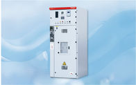
Metal Enclosed Fixed Electrical Switchgear Components Box Type

Product Details
| Model Number | XGN66-12 | Color | White/stainless Steel/customized |
|---|---|---|---|
| Application | Electric Power Transmission | Rated Voltage | Construction Electrical Control Box |
| Rated Frequency | 630/1250A | Protection Level | IP3X |
| Highlight | Fixed Electrical Switchgear Components,Box Type Electrical Switchgear Components,Construction Electrical Switchgear Components |
||
Product Description
XGN66-12 Box-type fixed metal-enclosed switchgear
Product description
XGN66-12 box-type fixed AC metal-enclosed switchgear (hereinafter referred to as switchgear) is suitable for 3.6~12k V three-phase AC 50Hz system as a device for receiving and distributing electric energy, suitable for frequently operated places and equipped with oil switches Used for the transformation of the switch cabinet. The bus system is a single bus system and a single bus section system.
The switchgear meets the requirements of GB3906 "3.6-40.5kV AC Metal-enclosed Open Sky Equipment and Control Equipment" and DL404 "Technical Conditions for Ordering Indoor AC High Voltage Switchgear". The switchgear has beautiful appearance, small size and complete and reliable misoperation prevention. Features. The main switch installed in the switchgear is VS1-12 or ZN28-12 vacuum circuit breaker, the isolation switch adopts the GN30-12, GN19-10 type isolation switch, and the grounding switch adopts the JN15-12 type grounding switch.
Model and its meaning
![]()
①Box structure
②Fixed
③Indoor
④Design serial number
⑤Rated voltage (kV)
⑥Main circuit scheme code
Conditions of Use
• Ambient temperature: highest +40°C, lowest -15°C;
• Altitude: not more than 1000m;
•Relative humidity: the daily average value is not more than 95%, and the monthly average value is not more than 90%;
• The earthquake intensity does not exceed 8;
• There is no fire, explosion hazard, severe pollution, chemical corrosion and severe vibration.
Technical Parameters
| name | unit | parameter |
| Rated voltage | KV | 3.6, 7.2, 12 |
| Rated current | A | 630, 1250 |
| Rated short-circuit breaking current | KA | 20, 25, 31.5 |
| Rated short-circuit making current | KA | 50, 63, 80 |
| Rated short-time withstand current (4s effective value) | KA | 20, 25, 31.5 |
| Rated peak withstand current (peak value) | KA | 50, 63, 80 |
| Imin power frequency withstand voltage | KV | 42 |
| Lightning impulse withstand voltage | KV | 75 |
| Auxiliary circuit 1 minT frequency withstand voltage | KV | 2 |
| Protection level | IP3X | |
| Dimensions (cable outlet, width X depth X height) | mm | 900x1000x2300 |
Installation dimension drawing
![]()
1. Cabinet door
2. Lighting
3. Observation window
4. Operating mechanism
5. Small door panel
6. Instrument door
7, brow
8. Busbar through wall bushing
9. Bolt
10. Replenishment
11. Washer
12. Nut
13. Isolating switch
14. Pull rod
15. Rear sealing plate
16. Current transformer
17. Vacuum circuit breaker
18. Isolating switch
19. Sensor
20. Bolt
21. Replenishment
22. Replenishment
23. Skeleton
24. Lightning arrester
Need to know when ordering
The user needs to provide the following information if ordering:• A wiring plan diagram and a wiring plan arrangement diagram.
• Secondary circuit schematic diagram, wiring diagram, terminal wiring diagram.
• List of primary and secondary equipment.
• The layout of the switch cabinet and the installation position of the busbar bridge.
• Please consult with our company for special conditions of use of spare parts and equipment.
Recommended Products